TEXTILES.ORG
Company:
Hallaton Environmental Linings Sparks, MD
Project Details
Fabric 1
Geomembrane
Producer:
Seaman Corp.
Supplier:
Seaman Corp.
Fabric 2
OTHER
Producer:
SKAPS Industries
Supplier:
SKAPS Industries
Project Manager Name
Scott Brinkerhoff
Project Manager Company
Hallaton Environmental Linings
Installation Name
Mauricio Sanchez
Installation Company
Hallaton Environmental Linings
Please describe the project specifications
IFAI AWARDS ENTRY
Installer: HALLTON ENVIRONMENTAL LININGS
Project Name: Druid Hill Reservoir-Temporary Lined Stone Cofferdam
Project Description
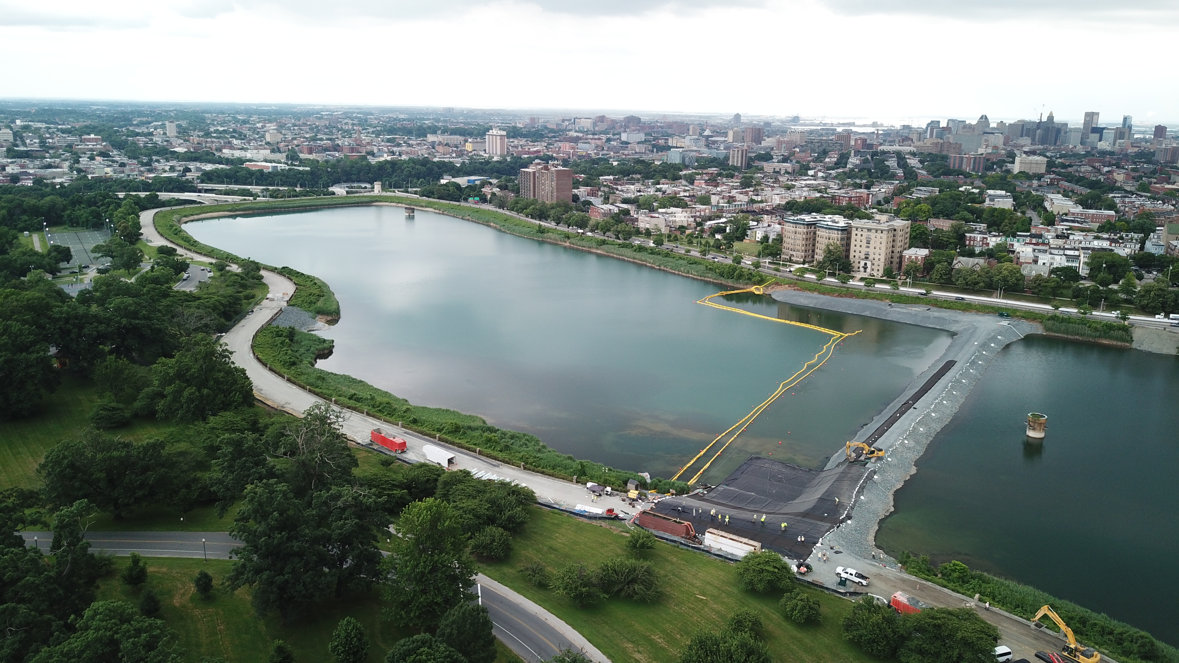
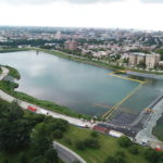
Our Company located in Sparks, Maryland is proud to have installed the geosynthetic liner portion of a temporary stone cofferdam at the iconic Baltimore location of Druid Hill Park in June 2018. Druid Hill Park was inaugurated in the year 1860, is 745 acres in size and is listed on the National Register of Historic Places. It is home to Druid Lake. Between the years 1863-1871, Druid Lake was constructed to provide a one-billion-gallon capacity, 55- acre fresh water reservoir. It remains one of the largest earthen dammed lakes in North America and in 1971 it was named a National Historic Civil Engineering landmark by the American Society of Engineers. Druid Hill Reservoir supplies the City of Baltimore and the surrounding counties with drinking water. The lined temporary stone cofferdam was a critical component of a much larger, $164 million-dollar five-year project to modify the existing Druid Hill Reservoir.
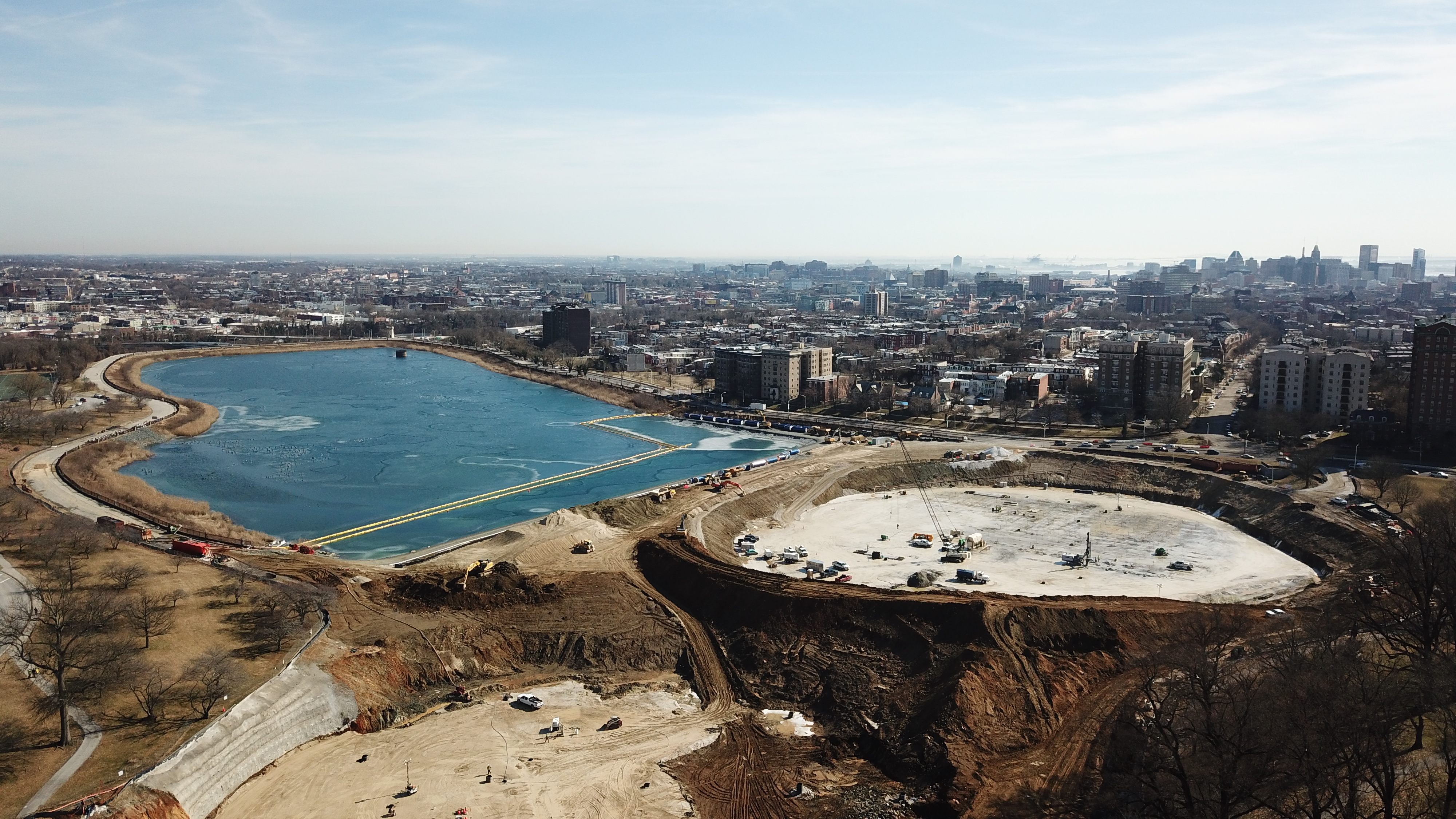
Currently, Druid Hill Reservoir is an exposed water storage system. Due to new federal government drinking water regulations to keep the drinking water protected from potential contaminants, Baltimore City decided to install two precast, pre-stressed water storage tanks (400-550 feet in diameter) underground in the western end of the original Druid Lake. The area above the newly installed buried tanks will be turned into a lawn for general park use. The newly installed underground tanks will allow the city to treat and store the “finished” chlorinated water more efficiently while maintaining the historic landscape of Druid Hill Park. The eastern part of the existing Druid Lake will be reduced by 6.3 acres and will remain an ornamental lake in keeping with the existing Park setting.
In 2016 a General Contractor was selected to construct the massive $164 million-dollar, five-year construction project. Included in the overall contract value was $6.7 million for engineering costs the General Contractor would need for various design-build components of the overall project. One of the critical components that needed additional engineering and design was a proposed temporary cofferdam. The temporary cofferdam was needed to maintain the current operations and to construct other key pieces of the overall project. Firstly, hold back and maintain for use the exposed pretreated drinking water for use by area citizens. Secondly, create a temporary barrier to allow the general contractor to dewater the western half of the existing reservoir in advance of constructing the underground water storage tanks.
Following the contract award, the General Contractor reached out to our Company in 2017 about providing a geosynthetic liner solution for a temporary stone cofferdam in which the General Contractor was proposing for use. The lined stone cofferdam would be constructed in lieu of a more traditional sheeting barrier system that was part of the original bid documents. The General Contractor and our Company in conjunction with the supplier proposed to install a temporary lining on one face of a stone cofferdam which was 1,200 feet in total length. The stone cofferdam varied in depth based on the existing reservoir bottom ranging from 0’ feet to 60’ thusly, the depth of water varied in the area where the temporary cofferdam would be constructed. The General Contractor and our Company consulted with an Engineering Firm to provide an engineering design for the proposed lined stone cofferdam concept.
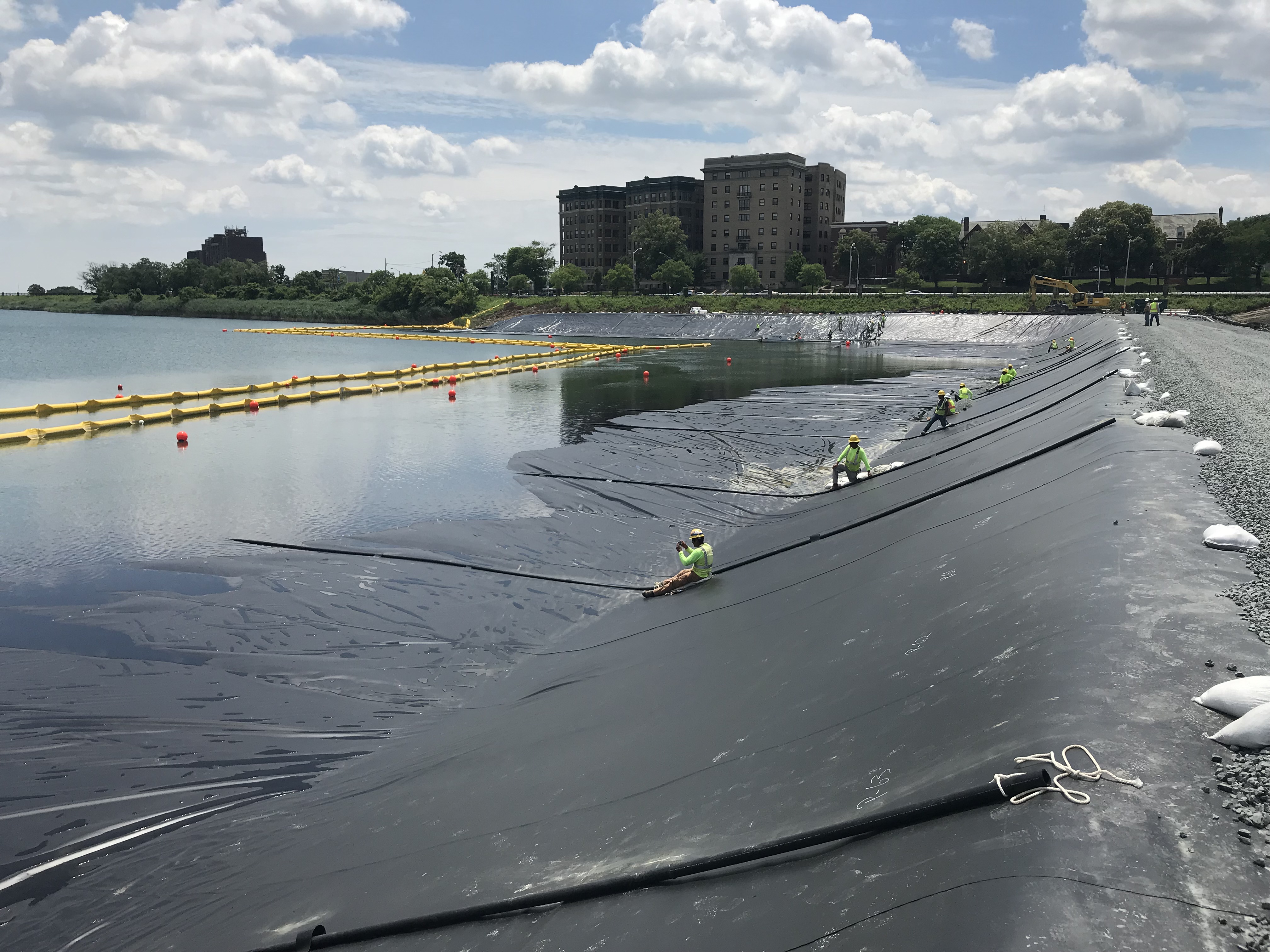
With a design in hand, our Company strategically chose a XR-3 8138 Potable Water grade geomembrane liner as manufactured by Seaman Corporation. It met the requirements for potable grade material, therefore it was compatible with drinking water. Additionally, the XR-3 is very puncture-resistant to survive the installation process with the angular rip-rap type stone cofferdam. Number 57 type stone were also utilized to minimize the angular surfaces. Another key factor in choosing the XR-3 geomembrane liner was its density. Its density is higher than water which made it possible to sink the liner. Our Company also proposed utilizing a double-sided geocomposite supplied by SKAPS to be installed directly on the stone cofferdam prior to installing the XR-3 geomembrane liner. Additionally, a piping system with hardware was proposed to be attached to the leading edge of the XR-3 geomembrane panels to assist with floating the geomembrane on top of the water on the eastern part of the reservoir. The piping system was comprised of 6” Schedule 40 solid wall PVC pipe with end caps installed along the entire leading edge of the deployed XR-3 panels. The other key component of the piping system was the installation of multiple 2” HDPE pipe runs that were installed on top of the XR-3 panels at varying intervals of the cofferdam. The 2” HDPE pipe lengths varied but were as long as 140 feet. Fabricated pipe loops were installed using XR-3 and the 2” HDPE pipes were proposed to be fed through the series of loops from the top of the cofferdam to the leading edge of the liner panels situated in the water. The amount of work access on the pipe float side of the fabricated liner was extremely limiting, ranging from 5-10 feet. The 2” HDPE pipes were proposed to be hooked to the edge of the floating liner opposite of the stone cofferdam during the liner deployment phase and when sinking the liner.
The General Contractor installed the washed stone portion of the cofferdam from north to south in direction across the reservoir. The base width of the cofferdam varied in width from 50’ to 160’. The height of the cofferdam varied from 3’ to 48’. The width at the top of the cofferdam was in the 20’-22’ range. The General Contractor installed the washed stone with excavators and off-road trucks. Turbidity curtains were installed in near the stone cofferdam to maintain the drinking water requirements. Turbidity issues presented a challenge to the project during the washed stone placement portion of the cofferdam. Multiple buoys were put in place to identify the depth of water and to locate the leading edge of the stone cofferdam below the water line.
With the stone portion cofferdam in place, Hallaton mobilized in June 2018 to begin the installation of the temporary liner system on the leading face. Our Company’s crew consisted of 14 field technicians and a field supervisor. The project was managed by our Company’s Vice-President, Scott Brinkerhoff. Other Company team members who assisted within the overall project were Owner, Todd Harman and Director of Operations, Justin Harward.
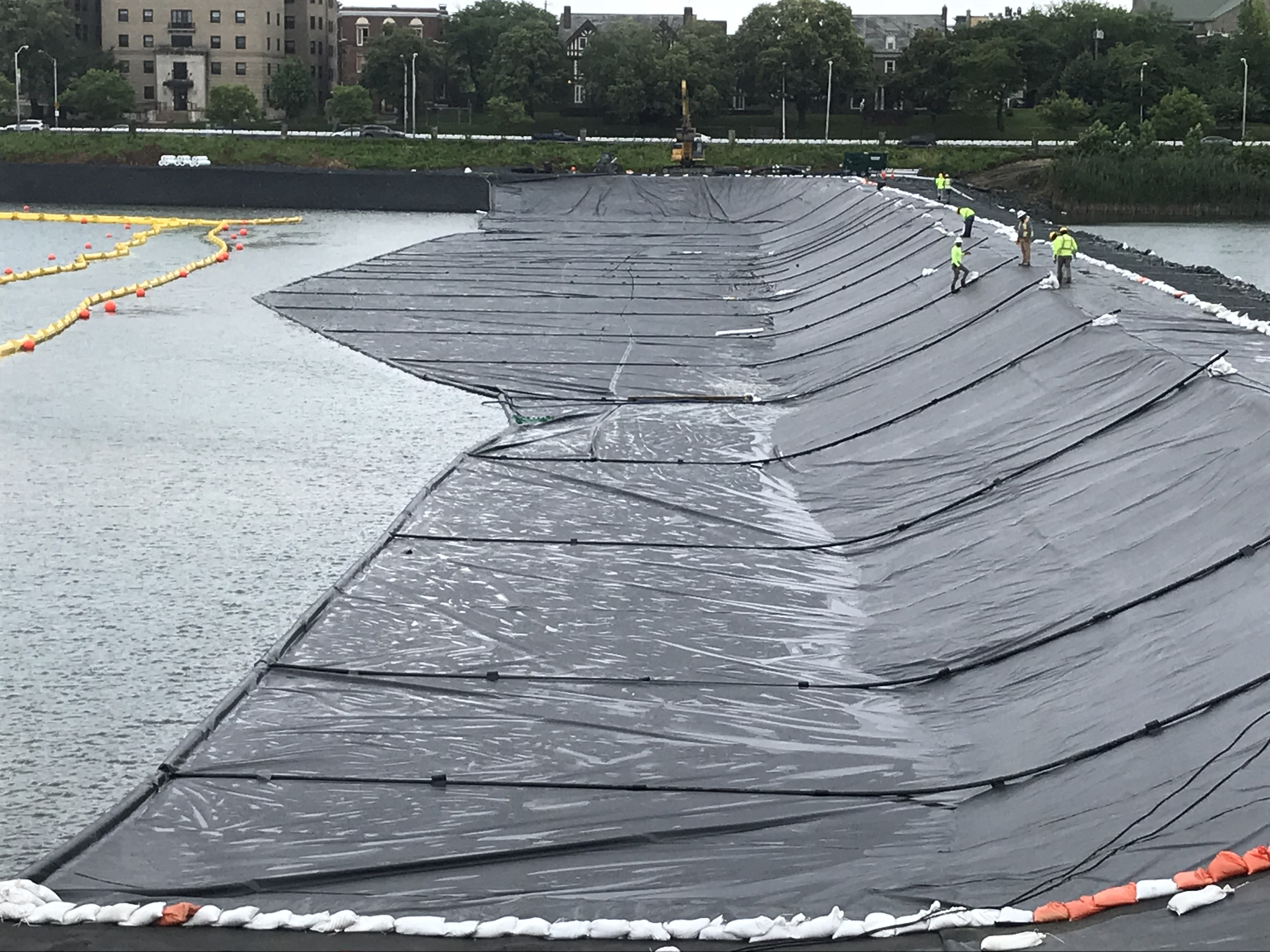
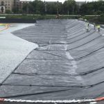
Our Company’s crew installed the geocomposite on the top of the stone cofferdam and the leading face down to, just above the existing water line. The geocomposite could not come in contact with the water since it was not potable grade. Our Company’s crew field fabricated panels of XR-3 as manufactured by Seaman Corporation in a staging area directly adjacent to the stone cofferdam.
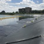
The installed stone cofferdam varied in width and depth over the entire length, this presented a big challenge. Each XR-3 field fabricated panel varied in length and had to measured and cut precisely to ensure the leading edge of the cofferdam would be covered after the liner system was sunk below the water line. Each panel length had to coincide with the exact width and depth of the stone cofferdam spanning the 1,200 feet length. With some of the piping system components in place, Our Company and the General Contractor began to pull the XR-3 panels across the water on the leading edge of the cofferdam and half way across the top of the stone portion of the cofferdam. As the field fabricated XR-3 panels were floated across the water, additional panels were fabricated on the shoreline and welded to the previously deployed panels. The number of panels pulled out varied from day to day.
Another project challenge was to keep the liner afloat as it was incrementally being pulled out across the water and cofferdam prior to being sunk into place. In case of heavy rains, multiple pumps were at the ready to pump water off the top of the floating liner. If too much water were sitting on top of it, it would start to sink prematurely. Additional challenges were working in an area where water was always present and the proximity of the turbidity curtains to the cofferdam. Our Company’s technicians utilized electric motorized boats during the installation process when floating the liner across the water. This presented us with an additional site-specific safety challenge. Our crews were up to the task.
The next challenge was to make the “turn”. The overall length of the cofferdam was 1,200 feet. However, it was not a straight run. The main section was approximately 900-feet in length followed by a 300-foot section along the southern side of the reservoir. Our Company had to field fabric the panels in the proximity of the 300-foot section. Our technicians had to fabricate the 300- foot liner panel run and then thermally fuse it to the end of the 900-foot main section liner that was previously pulled into place. Our technicians worked from boats to weld at the water line. They also utilized large block shaped floats wrapped in XR-3 as platforms to stand on to weld together the XR-3 panels in proximity of the “turn”. The tie-in at the “turn” of the 300-foot and 900-foot was successfully completed.
One of the final challenges to ensure the successful installation of the liner system was the sinking of the liner. Based on the proximity of the turbidity curtains, the sinking of the installed liner system needed to be controlled from the stone cofferdam. The piping system fabricated and installed by Hallaton was crucial to sinking the liner. As previously mentioned, the amount of work access on the pipe float side of the fabricated liner was extremely limiting, ranging from 5-10 feet. The 2” HDPE pipes were used to hook to the edge of the floating liner opposite of the stone cofferdam during the liner deployment phase and when sinking the liner. Hallaton’s crew worked systematically from boats to drill holes into the 6” Schedule 40 PVC pipes located on the leading edge. Water filled the 6” pipes creating ballast at the leading edge. The 2” HDPE piping system situated on top of the liner system was in place and connected to the leading edge 6” PVC pipe. Crew members were stationed on the cofferdam at the end of each 2’ HDPE pipe. The piping system was adjusted simultaneously at the predetermined intervals to allow water to flow within the 6” piping system which in turn starting the sinking of the leading edge of the floating liner. The liner system sunk to the bottom of the reservoir and cofferdam over the course of several hours. Following the successful sinking of the liner, divers were employed to enter the water to make sure the liner was in contact with the cofferdam below the water line. The divers inspected the sunken liner system and modified it accordingly to ensure intimate contact with the stone cofferdam over the entire length and varying depths.
Once the leading-edge liner system critical component was in place, the temporary stone cofferdam was ready to go into service. The General Contractor installed additional stone ballast on top of the completed lined cofferdam per design. Within a few days of completion, the General Contractor readied their pumps to dewater the western side where the new underground tanks are to be constructed. The moment of truth was at this point. With the dewatering process underway, the water pumped from the western portion of the lake behind the cofferdam began to lower in level and the lined cofferdam held back the exposed water storage system. As the western side water level lowered from dewatering activities, the temporary cofferdam was serving it’s intended purpose. The temporary lined stone cofferdam held back the large body of drinking water on the leading-edge eastern side and the western side was able to be completely dewatered to allow for the excavation and construction of the new underground water tanks.
The overall Druid Hill Reservoir project is still ongoing and is scheduled to be completed in 2021. Our Company is extremely proud to have been the geosynthetics installer for the temporary lined stone cofferdam. We installed 120,000 square feet of XR-3 potable grade liner and 52,000 square feet of double-sided geocomposite as part of the temporary lined cofferdam. The geosynthetic liner installation phase of the project was completed in just under two weeks in June 2018. This was not a typical geosynthetics installation. It was a highly challenging and innovative liner installation which stretched many boundaries. Our Company in conjunction with our project partners successful completed the installation of the temporary lined stone cofferdam safely, on time and within budget. Once the entire project is complete, the drinking water at the Druid Hill Reservoir will not be exposed to potential contaminates. The City of Baltimore will have a contained system for a well-protected water system.
What was the purpose of this project? What did the client request?
The purpose of the project was to construct a temporary lined stone cofferdam within an operational drinking water reservoir in order to construct two new precast, pre-stressed water storage tanks (400-500 in diameter) underground. The construction and installation of the lined cofferdam allowed the City of Baltimore to keep operational 49 acres of a 55 acre drinking water reservoir while 6.3 acres of the reservoir could be dewatered behind the lined cofferdam to facilitate the construction of the underground storage tanks.
What is unique or complex about the project?
In 2016 a General Contractor was selected to construct the massive $164 million-dollar, five-year construction project. Included in the overall contract value was $6.7 million for engineering costs the General Contractor would need for various design-build components of the overall project. One of the critical components that needed additional engineering and design was a proposed temporary cofferdam. The temporary cofferdam was needed to maintain the current operations and to construct other key pieces of the overall project. Firstly, hold back and maintain for use the exposed pretreated drinking water for use by area citizens. Secondly, create a temporary barrier to allow the general contractor to dewater the western half of the existing reservoir in advance of constructing the underground water storage tanks.
Following the contract award, the General Contractor reached out to our Company in 2017 about providing a geosynthetic liner solution for a temporary stone cofferdam in which the General Contractor was proposing for use. The lined stone cofferdam would be constructed in lieu of a more traditional sheeting barrier system that was part of the original bid documents. The General Contractor and our Company in conjunction with the supplier proposed to install a temporary lining on one face of a stone cofferdam which was 1,200 feet in total length. The stone cofferdam varied in depth based on the existing reservoir bottom ranging from 0’ feet to 60’ thusly, the depth of water varied in the area where the temporary cofferdam would be constructed. The General Contractor and our Company consulted with an Engineering Firm to provide an engineering design for the proposed lined stone cofferdam concept.
With a design in hand, our Company strategically chose a XR-3 8138 Potable Water grade geomembrane liner as manufactured by Seaman Corporation. It met the requirements for potable grade material, therefore it was compatible with drinking water. Additionally, the XR-3 is very puncture-resistant to survive the installation process with the angular rip-rap type stone cofferdam. Number 57 type stone were also utilized to minimize the angular surfaces. Another key factor in choosing the XR-3 geomembrane liner was its density. Its density is higher than water which made it possible to sink the liner. Our Company also proposed utilizing a double-sided geocomposite supplied by SKAPS to be installed directly on the stone cofferdam prior to installing the XR-3 geomembrane liner. Additionally, a piping system with hardware was proposed to be attached to the leading edge of the XR-3 geomembrane panels to assist with floating the geomembrane on top of the water on the eastern part of the reservoir. The piping system was comprised of 6” Schedule 40 solid wall PVC pipe with end caps installed along the entire leading edge of the deployed XR-3 panels. The other key component of the piping system was the installation of multiple 2” HDPE pipe runs that were installed on top of the XR-3 panels at varying intervals of the cofferdam. The 2” HDPE pipe lengths varied but were as long as 140 feet. Fabricated pipe loops were installed using XR-3 and the 2” HDPE pipes were proposed to be fed through the series of loops from the top of the cofferdam to the leading edge of the liner panels situated in the water. The amount of work access on the pipe float side of the fabricated liner was extremely limiting, ranging from 5-10 feet. The 2” HDPE pipes were proposed to be hooked to the edge of the floating liner opposite of the stone cofferdam during the liner deployment phase and when sinking the liner.
The General Contractor installed the washed stone portion of the cofferdam from north to south in direction across the reservoir. The base width of the cofferdam varied in width from 50’ to 160’. The height of the cofferdam varied from 3’ to 48’. The width at the top of the cofferdam was in the 20’-22’ range. The General Contractor installed the washed stone with excavators and off-road trucks. Turbidity curtains were installed in near the stone cofferdam to maintain the drinking water requirements. Turbidity issues presented a challenge to the project during the washed stone placement portion of the cofferdam. Multiple buoys were put in place to identify the depth of water and to locate the leading edge of the stone cofferdam below the water line.
With the stone portion cofferdam in place, Hallaton mobilized in June 2018 to begin the installation of the temporary liner system on the leading face. Our Company’s crew consisted of 14 field technicians and a field supervisor. The project was managed by our Company’s Vice-President, Scott Brinkerhoff. Other Company team members who assisted within the overall project were Owner, Todd Harman and Director of Operations, Justin Harward.
Our Company’s crew installed the geocomposite on the top of the stone cofferdam and the leading face down to, just above the existing water line. The geocomposite could not come in contact with the water since it was not potable grade. Our Company’s crew field fabricated panels of XR-3 as manufactured by Seaman Corporation in a staging area directly adjacent to the stone cofferdam.
The installed stone cofferdam varied in width and depth over the entire length, this presented a big challenge. Each XR-3 field fabricated panel varied in length and had to measured and cut precisely to ensure the leading edge of the cofferdam would be covered after the liner system was sunk below the water line. Each panel length had to coincide with the exact width and depth of the stone cofferdam spanning the 1,200 feet length. With some of the piping system components in place, Our Company and the General Contractor began to pull the XR-3 panels across the water on the leading edge of the cofferdam and half way across the top of the stone portion of the cofferdam. As the field fabricated XR-3 panels were floated across the water, additional panels were fabricated on the shoreline and welded to the previously deployed panels. The number of panels pulled out varied from day to day.
Another project challenge was to keep the liner afloat as it was incrementally being pulled out across the water and cofferdam prior to being sunk into place. In case of heavy rains, multiple pumps were at the ready to pump water off the top of the floating liner. If too much water were sitting on top of it, it would start to sink prematurely. Additional challenges were working in an area where water was always present and the proximity of the turbidity curtains to the cofferdam. Our Company’s technicians utilized electric motorized boats during the installation process when floating the liner across the water. This presented us with an additional site-specific safety challenge. Our crews were up to the task.
The next challenge was to make the “turn”. The overall length of the cofferdam was 1,200 feet. However, it was not a straight run. The main section was approximately 900-feet in length followed by a 300-foot section along the southern side of the reservoir. Our Company had to field fabric the panels in the proximity of the 300-foot section. Our technicians had to fabricate the 300- foot liner panel run and then thermally fuse it to the end of the 900-foot main section liner that was previously pulled into place. Our technicians worked from boats to weld at the water line. They also utilized large block shaped floats wrapped in XR-3 as platforms to stand on to weld together the XR-3 panels in proximity of the “turn”. The tie-in at the “turn” of the 300-foot and 900-foot was successfully completed.
One of the final challenges to ensure the successful installation of the liner system was the sinking of the liner. Based on the proximity of the turbidity curtains, the sinking of the installed liner system needed to be controlled from the stone cofferdam. The piping system fabricated and installed by Hallaton was crucial to sinking the liner. As previously mentioned, the amount of work access on the pipe float side of the fabricated liner was extremely limiting, ranging from 5-10 feet. The 2” HDPE pipes were used to hook to the edge of the floating liner opposite of the stone cofferdam during the liner deployment phase and when sinking the liner. Hallaton’s crew worked systematically from boats to drill holes into the 6” Schedule 40 PVC pipes located on the leading edge. Water filled the 6” pipes creating ballast at the leading edge. The 2” HDPE piping system situated on top of the liner system was in place and connected to the leading edge 6” PVC pipe. Crew members were stationed on the cofferdam at the end of each 2’ HDPE pipe. The piping system was adjusted simultaneously at the predetermined intervals to allow water to flow within the 6” piping system which in turn starting the sinking of the leading edge of the floating liner. The liner system sunk to the bottom of the reservoir and cofferdam over the course of several hours. Following the successful sinking of the liner, divers were employed to enter the water to make sure the liner was in contact with the cofferdam below the water line. The divers inspected the sunken liner system and modified it accordingly to ensure intimate contact with the stone cofferdam over the entire length and varying depths.
Once the leading-edge liner system critical component was in place, the temporary stone cofferdam was ready to go into service. The General Contractor installed additional stone ballast on top of the completed lined cofferdam per design. Within a few days of completion, the General Contractor readied their pumps to dewater the western side where the new underground tanks are to be constructed. The moment of truth was at this point. With the dewatering process underway, the water pumped from the western portion of the lake behind the cofferdam began to lower in level and the lined cofferdam held back the exposed water storage system. As the western side water level lowered from dewatering activities, the temporary cofferdam was serving it’s intended purpose. The temporary lined stone cofferdam held back the large body of drinking water on the leading-edge eastern side and the western side was able to be completely dewatered to allow for the excavation and construction of the new underground water tanks.
What were the results of the project?
The overall Druid Hill Reservoir project is still ongoing and is scheduled to be completed in 2021. Our Company is extremely proud to have been the geosynthetics installer for the temporary lined stone cofferdam. We installed 120,000 square feet of XR-3 potable grade liner and 52,000 square feet of double-sided geocomposite as part of the temporary lined cofferdam. The geosynthetic liner installation phase of the project was completed in just under two weeks in June 2018. This was not a typical geosynthetics installation. It was a highly challenging and innovative liner installation which stretched many boundaries. Our Company in conjunction with our project partners successful completed the installation of the temporary lined stone cofferdam safely, on time and within budget. Once the entire project is complete, the drinking water at the Druid Hill Reservoir will not be exposed to potential contaminates. The City of Baltimore will have a contained system for a well-protected water system.
Content is submitted by the participant. IFAI is not responsible for the content descriptions of the IAA award winners.