TEXTILES.ORG
Company:
Fabritecture (UFS Australasia Pty Ltd T/A Fabritecture) Gold Coast, QLD
Project Details
Fabric 1
FGT-600 PTFE
Producer:
Chukoh Chemical Industries Ltd.
Supplier:
Chukoh Chemical Industries Ltd.
Engineer Company 1
Wade Design
Design Company
Fabritecture
Architect Company
Westfield (Scentre Group)
Fabrication Company
TFS Textile Fabrication Services
Subcontractor Company
Fabritecture
Graphics Company
N/A
Project Manager Company
Fabritecture
Installation Company
Fabritecture
Please describe the project specifications
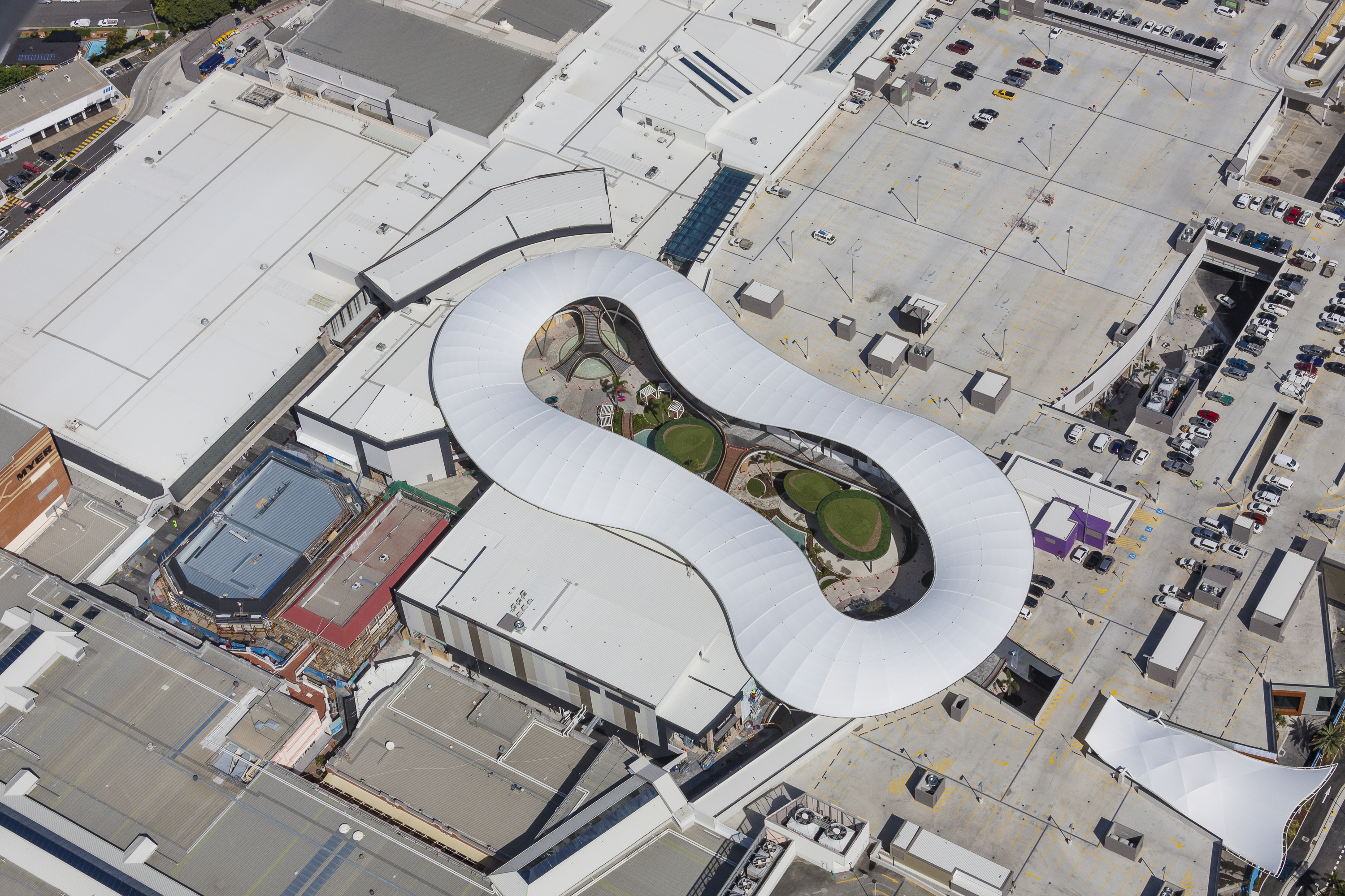
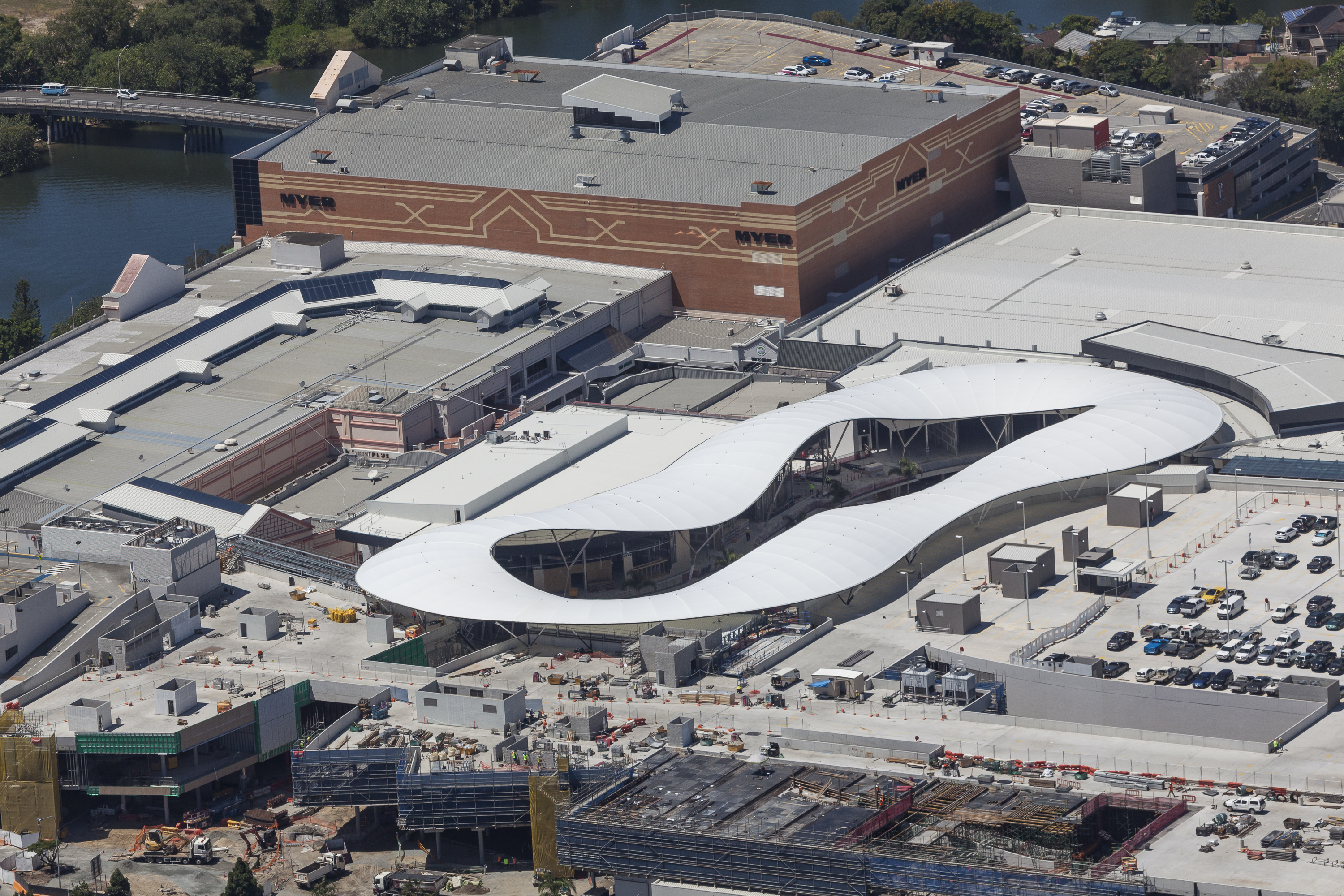
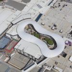
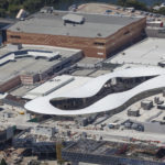
The Resort Roof project was part of the $670million Pacific Fair Shopping Centre redevelopment. The scope of the project was a complete design and construct of both steel and fabric for an architectural feature roof which was to cover the new resort area of the shopping centre.
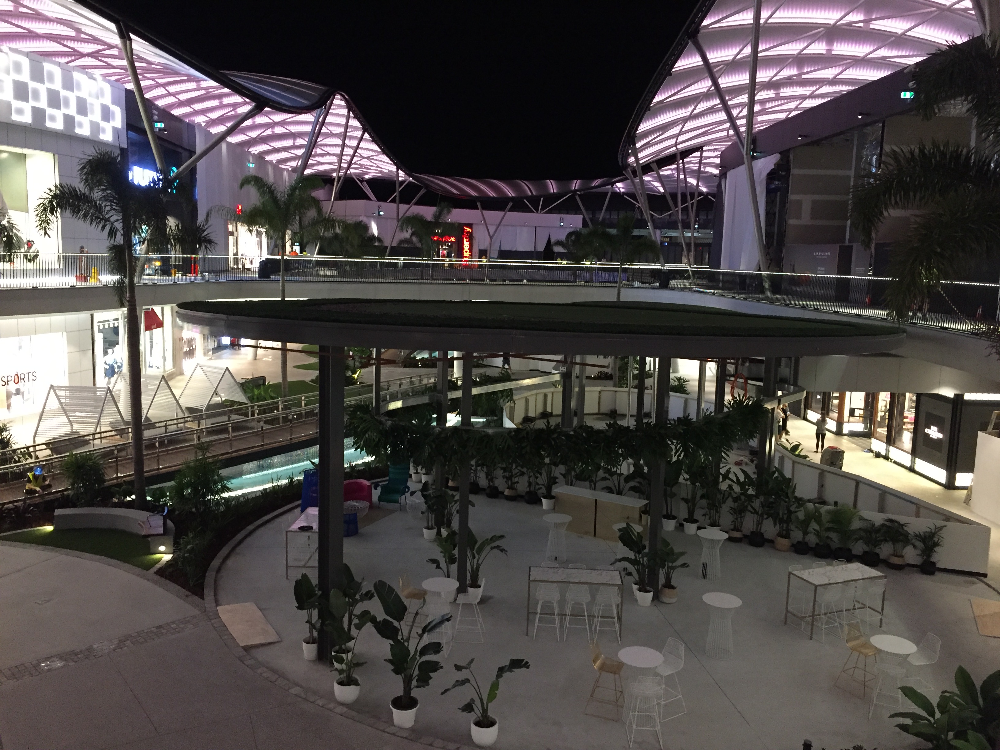
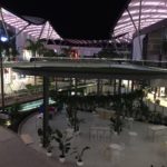
The roof is a 360 lineal meter dia-grid ribbon system with extreme curvature throughout. The iconic roof incorporates an LED lighting system throughout the entire structure which is capable of illuminating the entire structure together, or in alternating patterns.
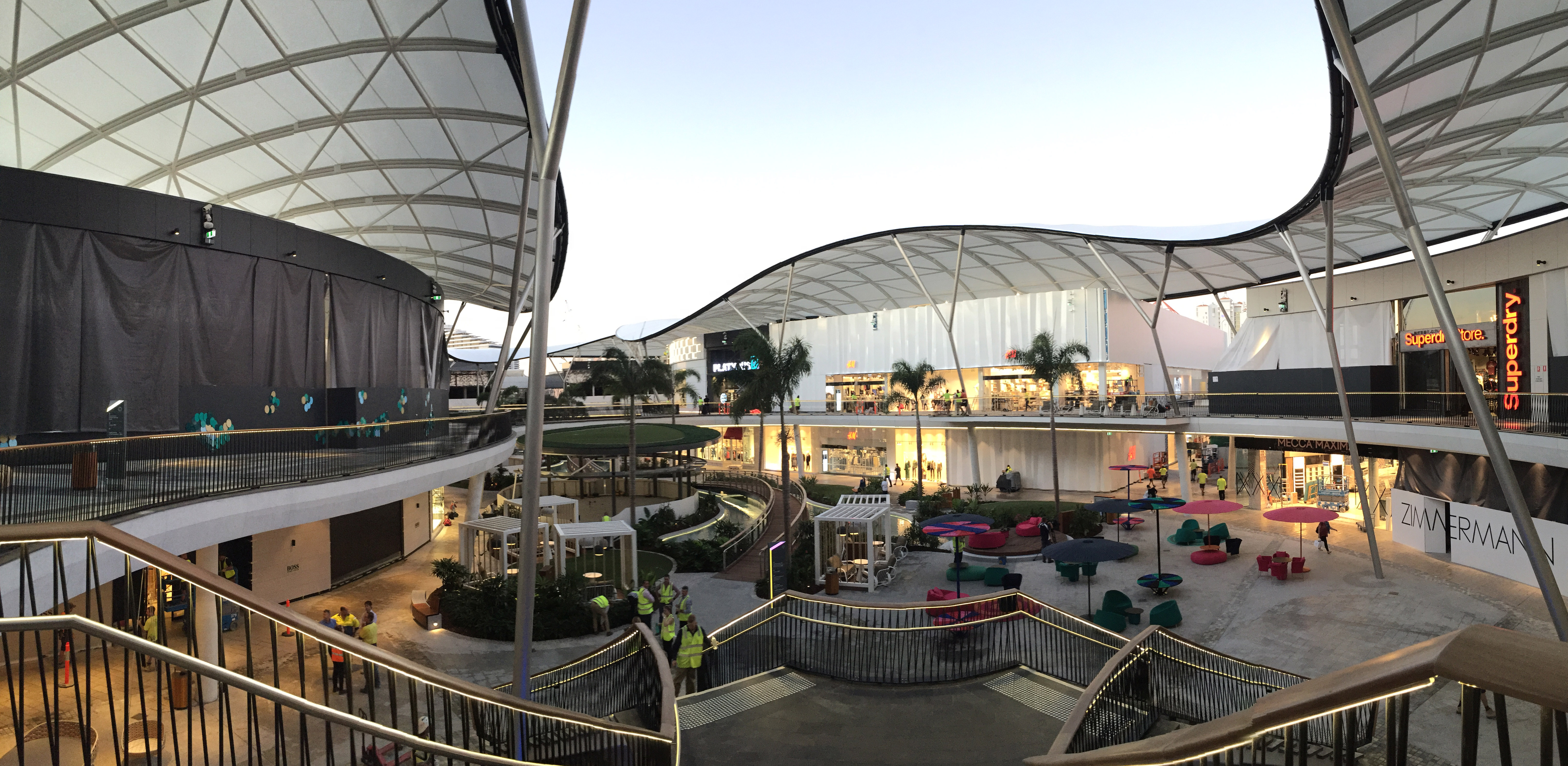
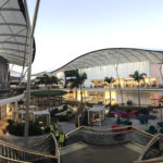
The roof was designed to become a key architectural feature for both the shopping centre, and the Gold Coast. The roof provides a functionally aesthetic, weatherproof solution to the open area, covering the first-level promenade. This allows the centre of the ground level to remain open and create an airy ambiance.
What was the purpose of this project? What did the client request?
The client requested an iconic structure that would help to drive Pacific Fair to become the Gold Coast’s ‘crown’ shopping centre. Pacific Fair now boasts the most innovative and unique architectural fabric structure of its kind on the Gold Coast. The structure was to become a statement feature to the resort area, hence the dia-grid style and crazy curvature as the main design principles.
The angled Y columns of the structure have been applied with the latest Quantum FX paint system. Specific locations for the Y columns were required due to the location of shop fronts.
The translucency of the fabric was requested to be high to simulate a bright, open ambiance below, while still providing adequate weather protection and shelter. The chosen PTFE fabric has low maintenance and high longevity properties.
What is unique or complex about the project?
This project was extremely complex, so naturally we encountered a few challenges along the way. During installation, there were many other trades sharing the same site. Considering the site was basically enclosed by the existing infrastructure of the shopping centre, access was limited. This tight situation made an extremely complex installation methodology even more complicated.
The geometry of the steel was a considerable challenge. We had been involved in the design of this project in the conceptual stage back in 2013. Right from the beginning, the client desired to push the boundaries of the geometry to create a unique structure. Grasshopper Parametric 3D modelling software was used to explore different options of the geometry. The decision was narrowed down to two options: the Wave Orthogonal and the Wave Diagonal. We completed the preliminary engineering on the fabric and provided the client advice on the Buildability of each design option. The Wave Orthogonal option was selected. The Wave Diagonal option was deemed to be beyond the boundaries of steel fabrication possibilities.
The chosen design included the outer perimeter 3D curved edge beam (363m long), the outer edge 3D curved edge beam (265m long), 80 curved rafters spanning from the inner to outer edge, 316 struts connecting the rafters in 4 rings, 198 diagonal struts to create the dia-grid, 18 full-height Y columns supporting the inner and outer edges, and 19 other support points around the outer edge, comprising of 1-3 support struts.
The inner and outer edges were by far the most complex geometry challenge we experienced. These use a large number of tangential curves (40 for outer edge and 41 for the inner edge) which create the undulating curved geometry required once connected together. Teklar and AutoCAD were used to model the entire structure, which was then fed back into the client’s master Revit model to do a final check for geometry and clashes.
A major risk for the project was the fabrication of the steelwork. In order to overcome this challenge, we trial assembled the entire roof (excluding columns) in sections during fabrication. Each section was surveyed after trial assembly, and cross-checked against the theoretical geometry using the 3D model. The steelwork was then painted after fabrication, and then loaded into purpose-built cradles to be freighted to site. The 200 tonne of steel was then delivered to site in 27 cradles, matching the installation sequence.
The seams in the roof were required by the architect to match with the steelwork ring beams. We achieved this by using 9 concentric seam lines, which were aligned parallel with the struts connecting the rafters. The result was 10 patterns per bay, with a total of 790 different patterns.
The architect specified they did not want to see any connections in the steelwork throughout the structure. The only acceptable visible connections were pinned connections at the bases of some of the outer struts. In order to achieve this requirement, all connections were designed to fit within the overall shape of the member. Sheet metal cover plates were then installed to conceal the connections. Approximately 1,400 cover plates were installed throughout the entire structure.
Drainage and guttering posed their own challenges for us during installation. Three hundred half and round gutters were to be installed on the inner and outer. This created an issue as 300 half round sheet metal cannot be rolled. As a solution, the gutter was fabricated in approximately 900mm lengths, creating a faceted gutter by joining the gutter bracket. A ‘best fit’ method was used, and each gutter section was 3D modelled and shop detailed.
Each section of the structure is a wedge shape in plan, which allowed for the change in angle at each bracket. The installation was assisted by an intricate temporary bracing system, which was provided as an engineering solution. This was required for all of the columns to control where the structure was positioned while incomplete, during installation. Water is fed into the downpipes via the gutter, which is fabricated and concealed within the columns. The water is then directly plumbed into the stormwater drainage system.
A perfect installation was emphasised due to the ribbon ring shape of the structure. During the installation of the steelwork, a highly technical process was followed to ensure that the structure would meet at the join accurately to complete the ring. In order to achieve this, all lifts, connection points and landing points (i.e. columns, base plates and primary lifts) were carefully surveyed prior to being lifted into place. The edge beam was surveyed throughout the entire build to ensure a successful join at the end. The installation team was extremely particular about the process being followed exactly throughout the entire erection of the steel. This proved worth it during the final link up, with only 2 struts being half a bolt hole out.
What were the results of the project?
The end result of the project was an incredible success. Our installation team did an amazing job, with the final steel link-up almost perfect at only 7mm out!
The project exceeded the requirements of the brief and the client was extremely happy. As a result of this project, we were awarded another million dollar shopping centre redevelopment with the client.
The state-of-the-art LED lighting system is capable of illuminating the structure in both solid and alternating colours, which has made this structure a hot topic on many social media platforms after opening to the public.
Content is submitted by the participant. IFAI is not responsible for the content descriptions of the IAA award winners.